|
RCL-meter measures the complex impedance and calculates the resistance, capacitance or inductance of a component.
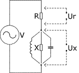
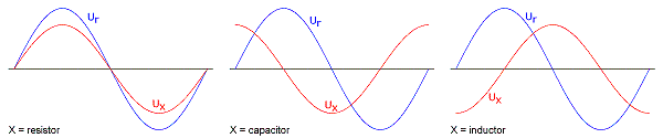
The working principle is simple: an AC voltage of a known frequency is applied over a known resistor (R) in series with an unknown impedance (X). Based on the value of R, the voltage ratio (Ux / Ur) and the phase shift between Ux and Ur the unknown impedance (X) can be determined.
So, apart from the reference resistor, one signal source and two phase sensitive voltmeters are required in order to measure impedances this way.
|
|
|
|
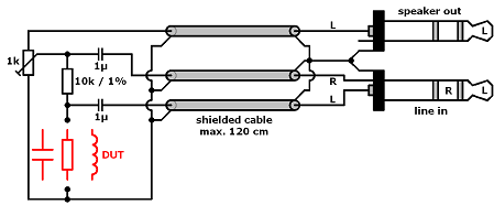
Here a sound card is used as signal source (the speaker out) and the two phase sensitive volt meters (ADC's incorporated in the left and right line inputs). One ADC measures the source signal while the other ADC measures the signal over the DUT (Device Under Test).
Knowing the exact value of R and the frequency of the signal source the value of the DUT can be calculated from the ratio of the amplitudes both ADC signals in combination with the phase shift between both signals.
Although this sounds simple, it certainly is not. At the frequencies used to measure, the impedance of the DUT can be as low as a fraction of an Ω or as high as 50 MΩ. In the first case the signal over the DUT will be very small while in the second case both ADC values will be almost identical. In addition the input impedance of the sound card inputs is rather low, causing a relatively small unwanted impedance in parallel with de DUT. As a result the DUT will introduce only an extremely small amplitude change and phase shift.
For example: Assume a sound card with a input impedance of 5 kΩ in parallel with 2 nF. A 10 pF capacitor as DUT will cause an amplitude decrease of less than 0.001 % and a phase shift of about 0.01°.
Such small amplitude changes or phase shifts cannot be measured directly. But it can be done by Fourier analysis of the signals and calculating amplitude change and phase shift from this data.
|

|
Resistance and capacitance measurements are performed at a frequency of 980 Hz, inductance measurements at a frequency of 11025 Hz (in order to allow the measurement of small inductances).
Specifications
Typical specifications using a high quality sound card are:
- Resistance
- Range: 1 Ω - 10 MΩ
- Accuracy: 2 % or 0.1 Ω, whatever is larger (5 % above 5 MΩ)
- Capacitance
- Range: 10 pF - 10 μF (non polarized)
- Accuracy: 2 % or 1 pF, whatever is larger (5 % above 1 μF)
- Inductance
- Range: 10 μH - 10 mH
- Accuracy: 2 % or 1 μH, whatever is larger
Measured values in the range of 0.1 Ω - 99.9 MΩ, 0.5 pF - 99.9 μF and 0.5 μH - 99.9 mH are displayed, but very low and very high values should be taken with caution.
Limitations
Keep in mind that the RCL-meter performance is limited by the quality of the sound card.
Furthermore all measurements are performed at audio frequencies. As a result the measurements may not be conclusive for high frequency applications of the DUT.
Read the help file for more information.
Copyright
This software is copyrighted freeware. This means that, although it is available for free, the author retains the copyright. You cannot do anything this software that is not expressly allowed by the author.
You are allowed to use it and/or distribute the unmodified installation file free of charge.
Any commercial use (including adding it to a commercial "software collection") is strictly prohibited without the prior written permission of the author.
Disclaimer
The author can not be held liable for any direct, indirect, consequential or incidental damages to other pieces of software, equipment, goods or persons arising from the use of this software and/or hardware.
It is strongly recommended to read and understand the safety precautions before using the RCL-meter.
Author
Rik Strobbe, on7yd@strobbe.org.
Read the help file file for more details.